


1. Background
Bolts are indispensable fastening connectors in daily life and industrial production they are also known as the rice of industry it can be seen that bolt is widely used. As common fastener the railway bolt will cause great vibration when the high-speed train and the rail are in constant contact. Once the bolt breaks suddenly or loosens in some key parts during the operation it will cause great danger to the high-speed railway. Due to the large number and various specifications of railway bolts it is an important guarantee for the quality of railway bolts to provide a fast and effective detection method.
2. Traditional inspection method of railway bolts
Nondestructive testing of railway bolts generally adopts ultrasonic testing penetrant testing and magnetic particle testing.
2.1 Ultrasonic testing
Ultrasonic testing of bolts can be divided into conventional A-scan ultrasonic testing and conventional phased array ultrasonic testing. Conventional ultrasonic testing is to determine the size and position of defects according to the amplitude and position of the reflected echo generated when the heterogeneous defects are encountered in the process of ultrasonic propagation in bolts.
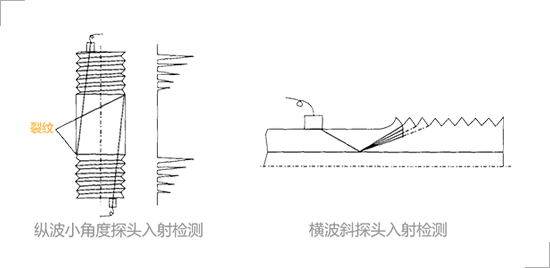
Fig. 1 Conventional ultrasonic inspection of bolts
Due to the special structure of bolts and the renewal of materials it is difficult to distinguish the defect wave and interference wave by conventional ultrasonic testing. However the conventional phased array ultrasonic testing technology is to cover the screw thread area of the bolt with the phased array linear scanning or sector scanning and the detection results inside the bolt are displayed graphically which can effectively detect the artificial defects inside the bolt.
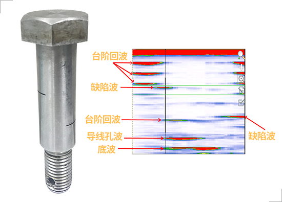
Fig. 2 Conventional PA B-scan ultrasonic testing
However in the results of conventional phased array ultrasonic testing the image feature difference between cracks and screw threads is not very obvious which may lead to misjudgment of defects.
2.2 Penetrant testing
The penetrant test of bolt is to apply penetrant on the surface of the inspected bolt workpiece under the capillary action the penetrant goes deep into the defects of the surface opening and then remove the redundant penetrant on the surface of the inspected bolt. After the appropriate imaging method is adopted under a certain light source (black light or white light) the opening defects of the inspected bolt are detected. Although the penetrant testing equipment of bolts is simple and easy to operate and the defects are not restricted by materials the penetrant testing can only detect the open defects on the bolt surface and has certain requirements for the surface state or cleanliness of the inspected bolt.
2.3 Magnetic particle testing
The magnetic particle testing of bolts is a nondestructive testing method to detect the defects on or near the surface of ferromagnetic materials through the accumulation of magnetic particles in the leakage magnetic field near the defects. Although the operation is simple and convenient the testing cost is low and it has high sensitivity to detect the surface and near surface defects of bolts but it can only detect the surface and near surface defects of bolts. It has high requirements on the surface smoothness high requirements on the technology and experience of inspectors small detection range and slow detection speed.
In summary the traditional inspection methods of bolts conventional ultrasonic and conventional phased array can be used for in-service inspection but they have high requirements for inspectors and have great influence on human factors while magnetic powder and penetration are not conducive to in-service inspection on site.
3. Phased array 3D total focus (TFM) detection method for railway bolts
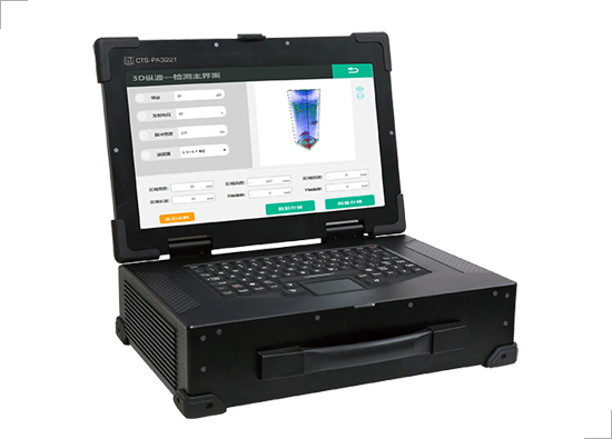
Fig. 3 Phased array total-focus real-time 3D ultrasonic imaging system CTS-PA322T
Inspection case of railway bolt:
Case 1: Railway bolt
In order to verify the flaw detection equipment and the feasibility of the flaw detection results the transverse groove shall be processed in different directions and positions according to the bolt size and the circumferential interval shall be 120 °. Using 3D TFM technology to detect high-strength alloy steel bolts (diameter 25mm length 130mm).
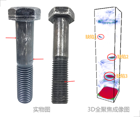
Fig. 4 3D total focus detection image of bolt
The CTS-PA322T system is equipped with a matrix array probe. When testing bolts it only needs to operate according to regulations. When the probe is placed at the end of the bolt (both ends) it does not need to move the probe and other operations. The CTS-PA322T system can collect all the information inside the detected bolt in real time and output the 3D detection image of the detected bolt in real time.

Fig. 5 Observation of all-round rotation
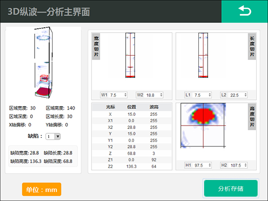
Fig. 6 Analysis & storage
3D total focus real-time detection imaging can be rotated for observation with simple defect identification and fast detection speed. The average detection time of a bolt is 2 seconds. The detection result is reliable and the damage is easy to observe which can effectively avoid the defect omission. Not only that the system provides the function of defect analysis and storage which can accurately locate and quantitatively measure the internal defects of the detected bolts.
Case 2: Connecting pin of balance wheel
When there is no defect in the connecting pin of balance wheel only the echo of conductor hole and bottom wave are detected:
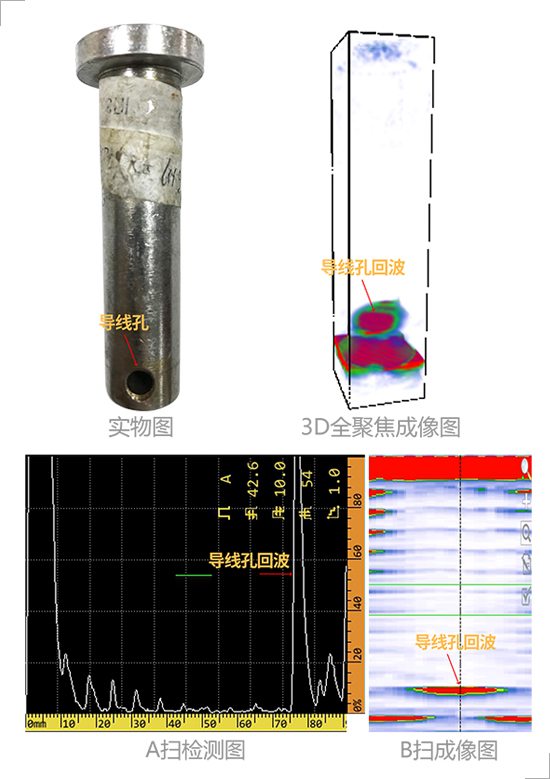
Fig. 7 Connecting pin of balance wheel (no defect)
The connecting pin of balance wheel has natural crack defect and the crack is large which can be seen by visual inspection. The comparison between the inspection result and the actual object:
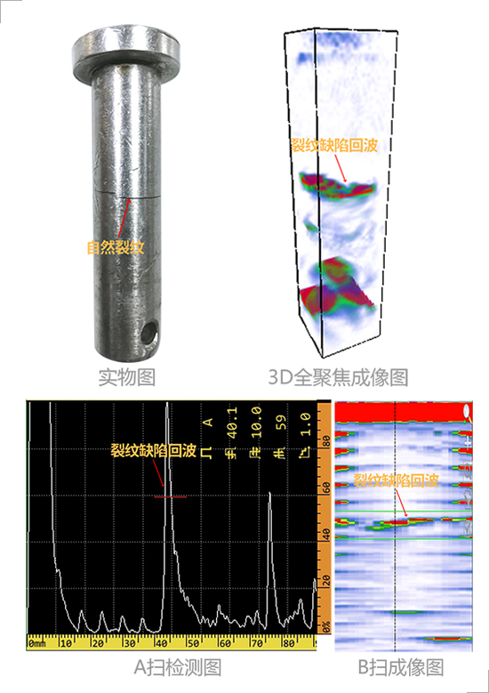
Fig. 8 Connecting pin of balance wheel (with natural crack 1)
The connecting pin of balance wheel has natural crack defect and the crack is small. The comparison between the inspection result and the actual object:

Fig. 9 Connecting pin of balance wheel (with natural crack 2)
No cracks and other defects are found on the connecting pin of balance wheel through visual inspection and micro cracks are found after inspection. The inspection results show that the detection sensitivity is high:

Fig. 10 Connecting pin of balance wheel (with natural crack 3)
Case 3: Connecting pin of lower anchor bracket
When there is no defect in the connecting pin of the lower anchor bracket only the echo of the conductor hole and the bottom wave are detected:
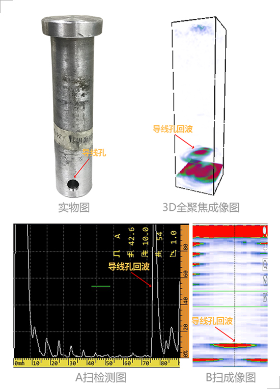
Fig. 11 Connecting pin of lower anchor bracket (no defect)
In order to verify the flaw detection equipment and the feasibility of the flaw detection results according to the size of the connecting pin of the lower anchor bracket the grooves with different depths are processed and the groove depth is 1mm:
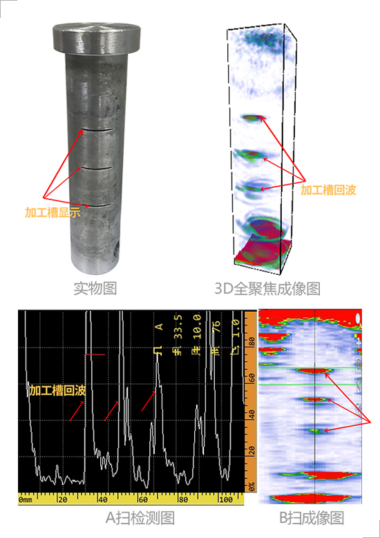
Fig. 12 Groove depth of connecting pin of lower anchor bracket (with artificial defects) 1mm
Case 4: Balance wheel axle pin
When there is no defect in the balance wheel axle pin only structural wave and bottom wave are detected:
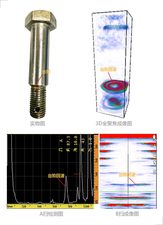
Fig. 13 Balance wheel axle pin (no defect)
According to the dimension of the balance wheel axle pin two grooves with different depths and directions are processed the groove depth is 1mm:
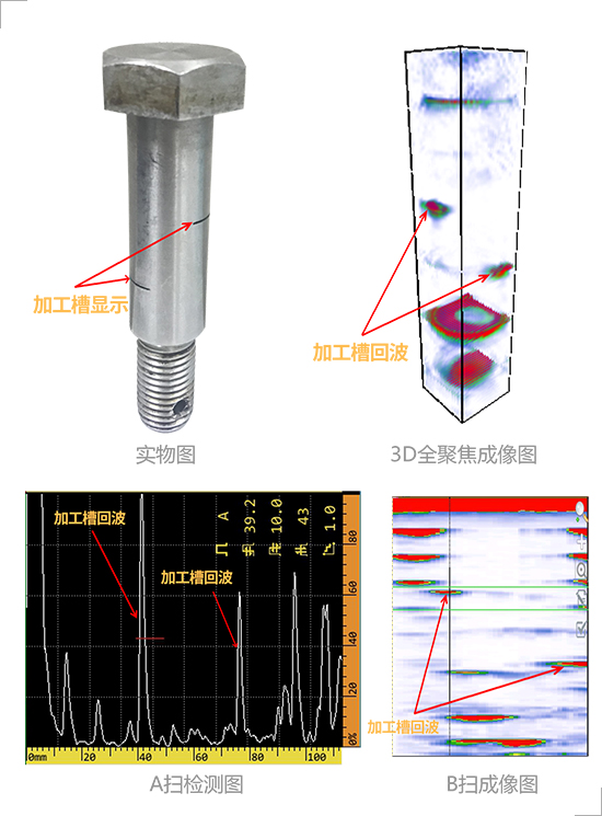
Fig. 14 Balance wheel axle pin (with artificial defect groove depth of 1mm)
According to the above cases through A-scan inspection chart B-scan image and 3D total focus technology inspection imaging in the pin without defects 3D total focus imaging chart only has conductor hole echo and bottom wave and conductor hole imaging is clear. For the pin with defects the echo waveform location and size of natural cracks can be observed by 3D total focus technology.
Although the location of the defect can be detected by A-scan inspection chart the waveform of the defect can be clearly displayed by B-scan imaging chart and 3D full focus imaging chart the structural wave and defect wave in A-scan inspection chart can only be judged by the depth of the echo and the feature difference between the structural wave and the crack echo in B-scan inspection is not very obvious which are easy to cause misjudgment or missing inspection while 3D full focus imaging chart can clearly distinguish the crack defect wave and structure wave. The image is three-dimensional the defect identification is simple the detection speed is fast and the validity of detection is improved.
The advantages of 3D total focus technology:
●Based on the two-dimensional array probe in three-dimensional space the defect information of the detected workpiece is collected from different spatial angles. The information collection is more sufficient the internal defects of the bolt are in a clear view the image is intuitive and reliable and the defect omission is avoided.
● Without moving the probe the real-time 3D imaging of the whole bolt can be realized and the observation can be rotated so the inspection results are more intuitive.
● The detection time of a bolt is less than 2 seconds and the detection efficiency is high.
● Up to 65536 focus points high image focusing accuracy.